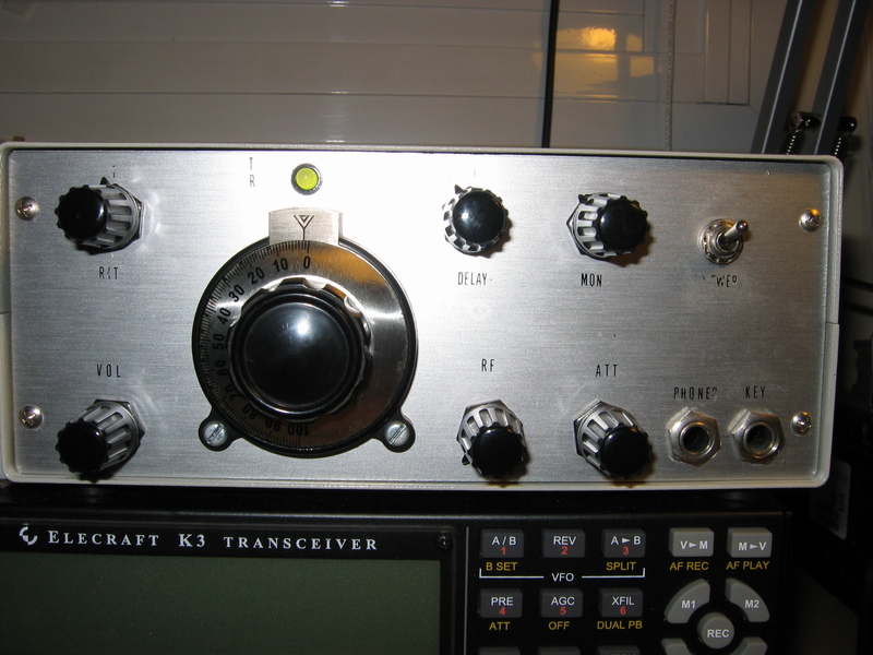
Intermodulation measurement in receivers is an useful thing for characterizing them. I am used to live with mediocre receivers. Since I was a youngboy I built several HF receivers, from direct conversion to superheterodine single conversion. All of them suffered intermodulation problems that were cured by adding some ammount of RF attenuator in the front end. At night, when commercial broadcast stations deliver strong signals at receiver input, the problem arises hard. That is a nasty problem. If you add attenuation before receiver front end, you rise the noise figure by the same ammount of the added attenuation. You loose the ability of copying weak signals.
During the last month, my concern has been improving the dynamic range of one of my receivers. The receiver is a single conversion, 8.867 MHz IF, 7 MHz CW receiver. At night, it suffers intermodulation from the broadcasters. Adding some attenuation with a potentiometer at the receiver input cures the intermodulation. I was curious about measuring intermodulation of this receiver to see how it compares to the commercial receivers I own.

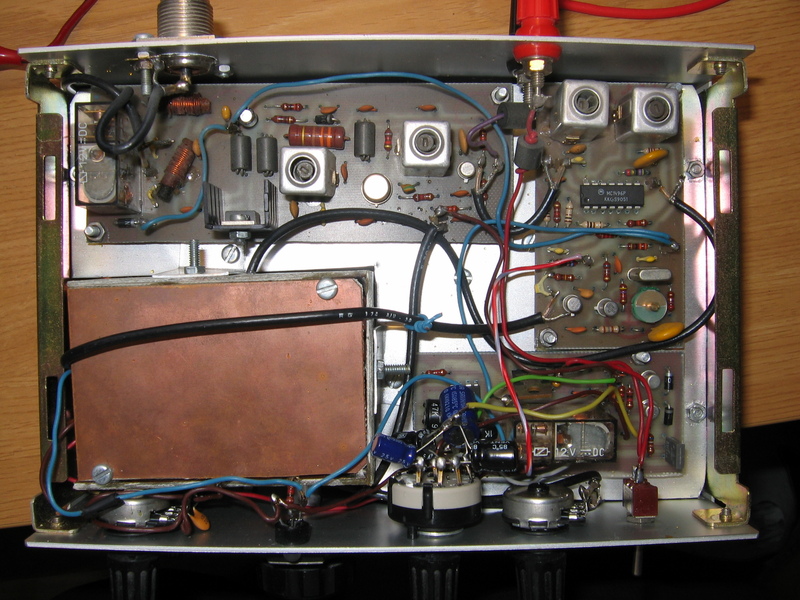
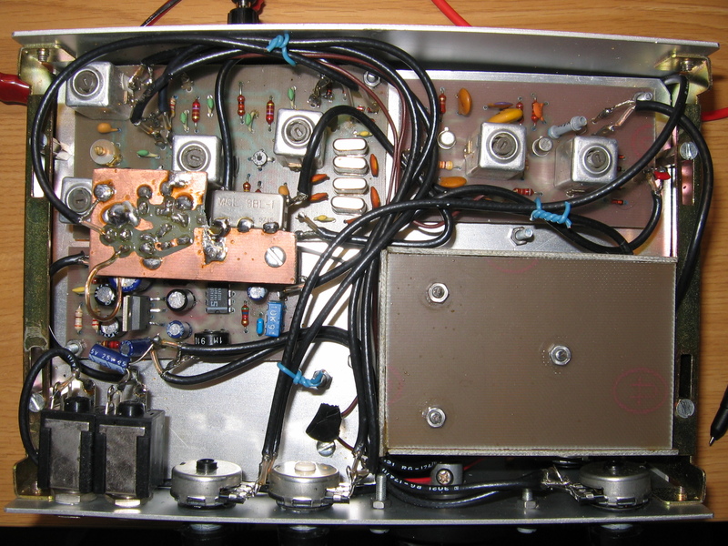
What do we want to measure? The first thing we need to measure is receiver noise floor. The MDS, or Minimum Discernible Signal (in dBm), is the signal level at receiver input that rises the noise floor by 3 dB. At that point, the signal and the noise have the same power. For this measurement, a bandwidth (BW) must be stablished cause the noise power depends on the BW. 500 Hz is a common BW used to make this measurement.
Now we must measure intermodulation. What is intermodulation? This is a difficult subject but in a a few words, when you feed a receiver with two signals of F1 and F2 frequencies and due to the lack of linearity of the receiver stages, a handful of signals are generated. We are going to measure the third order intermodulation products, that is, 2F1-F2 and 2F2-F1 signals. The SFDR or Spurious Free Dynamic Range (in dB) is the range from the MDS to the two tones signal level that produces an intermodulation product that rises 3 dB over the noise floor. Note that if signal level rises 1 dB, the IMD products rises 3 dB. IMD products will continue rising until they are the same level as the signals that originate them. That theoric point is called the Intercept Point, and it is a theoric point that cannot be reached cause the receiver saturates before.
Making MDS and SFDR tests in receivers requires calibrated instruments. Signal generators must be 50 ohm impedance. Generated signal must be sinusoidal with no harmonic content. Signal level must be known accurately. The way described here is a "poor man method" that will not produce exact results, but I think is useful enough to give some numbers and compare among the receivers I own at my radio shack.
We need:
-Two channel signal generator. I use two DDS units that I bought at very low price on Ebay. I modified them for having 50 ohm output impedance and a low pass filter to remove alias signals. I put them in a box and resulted a very handy unit. I will describe the modifications when have free time. Signal level is measured into a Rigol DS1052E 50 MHz BW oscilloscope. So, signal level accuracy depends on this measurement.
-6 dB hybrid combiner. This useful and easy to build device, combines the signals of both generators and provides isolation between them. I will also describe it in a future article. In the mean time, search in the Internet for "hybrid combiner" and enjoy, there is plenty of information.
-Step attenuator. I have built a 1-122 attenuator in 1 dB steps. This unit can be build easily with some patience.
-Audio detector for measuring receiver audio output in dB. In the old days it was done with a rectifier and a diode. Nowadays, the best way is using the sound card and Linrad, SM5BSZ software. Linrad can be used as a powerful spectrum analyzer as well as a general purpose SDR receiver.
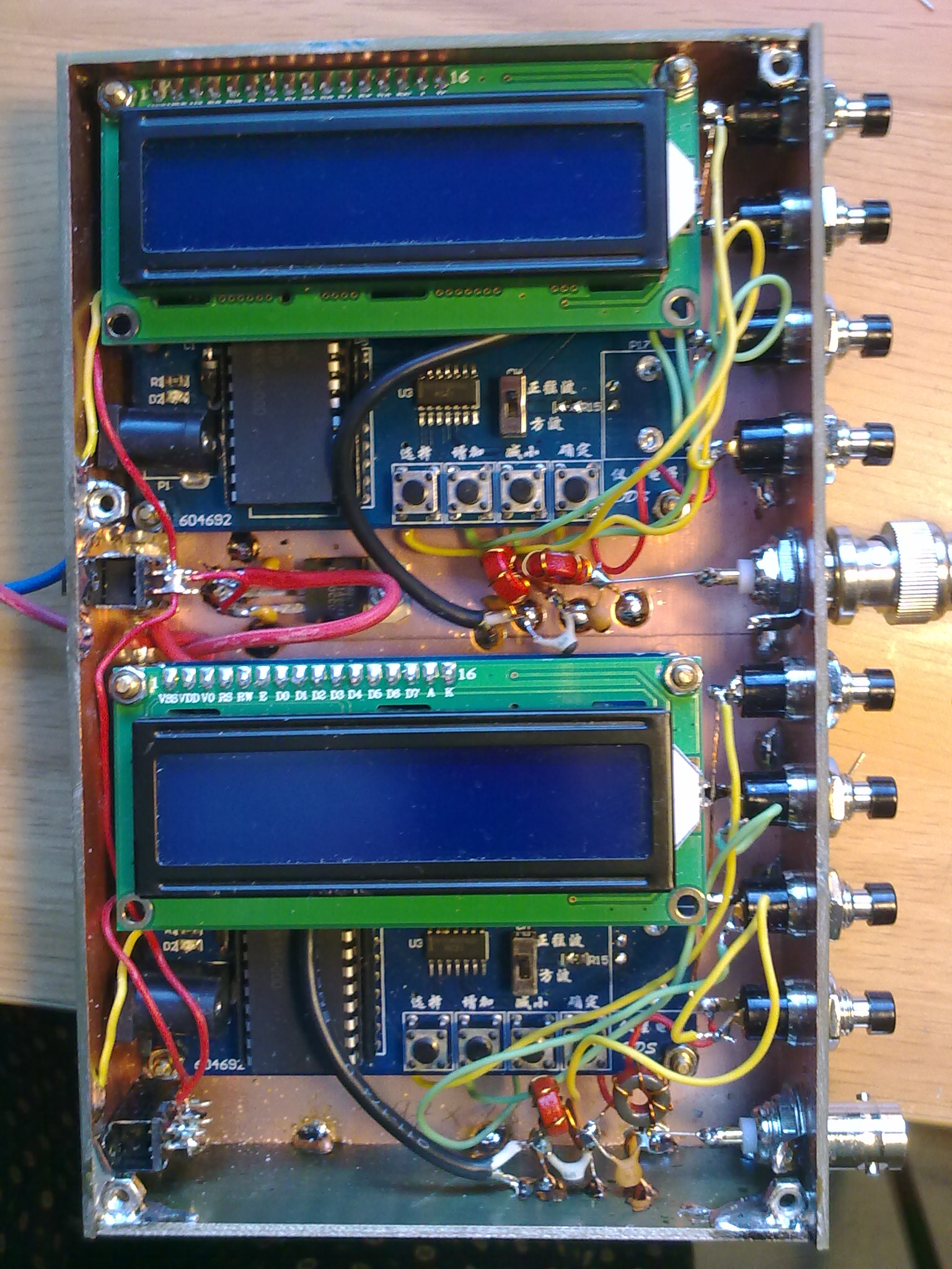 FIGURE4: INSIDE DUAL DDS SIGNAL GENERATOR
|
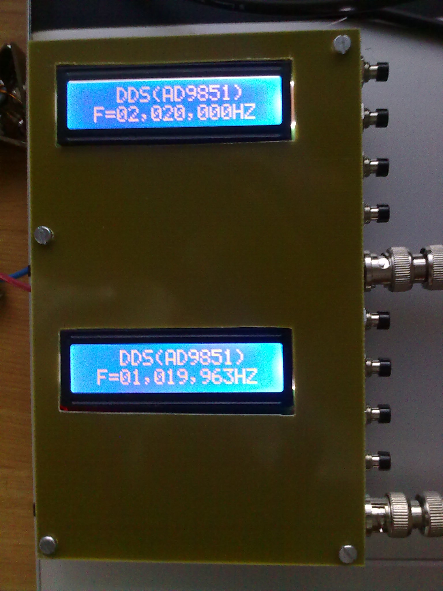 FIGURE5: DUAL DDS SIGNAL GENERATOR DISPLAY
|
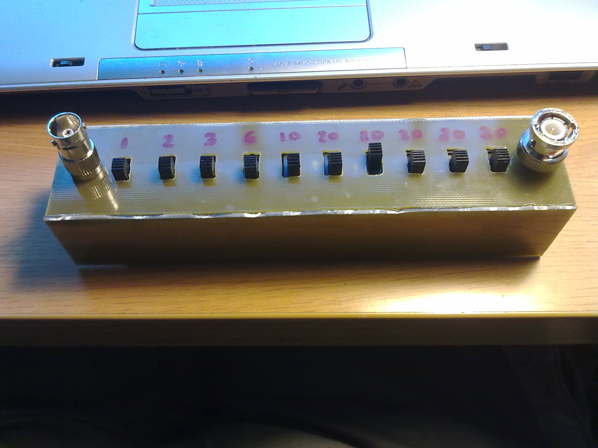 FIGURE6: 1-122 dB STEP ATTENUATOR
|
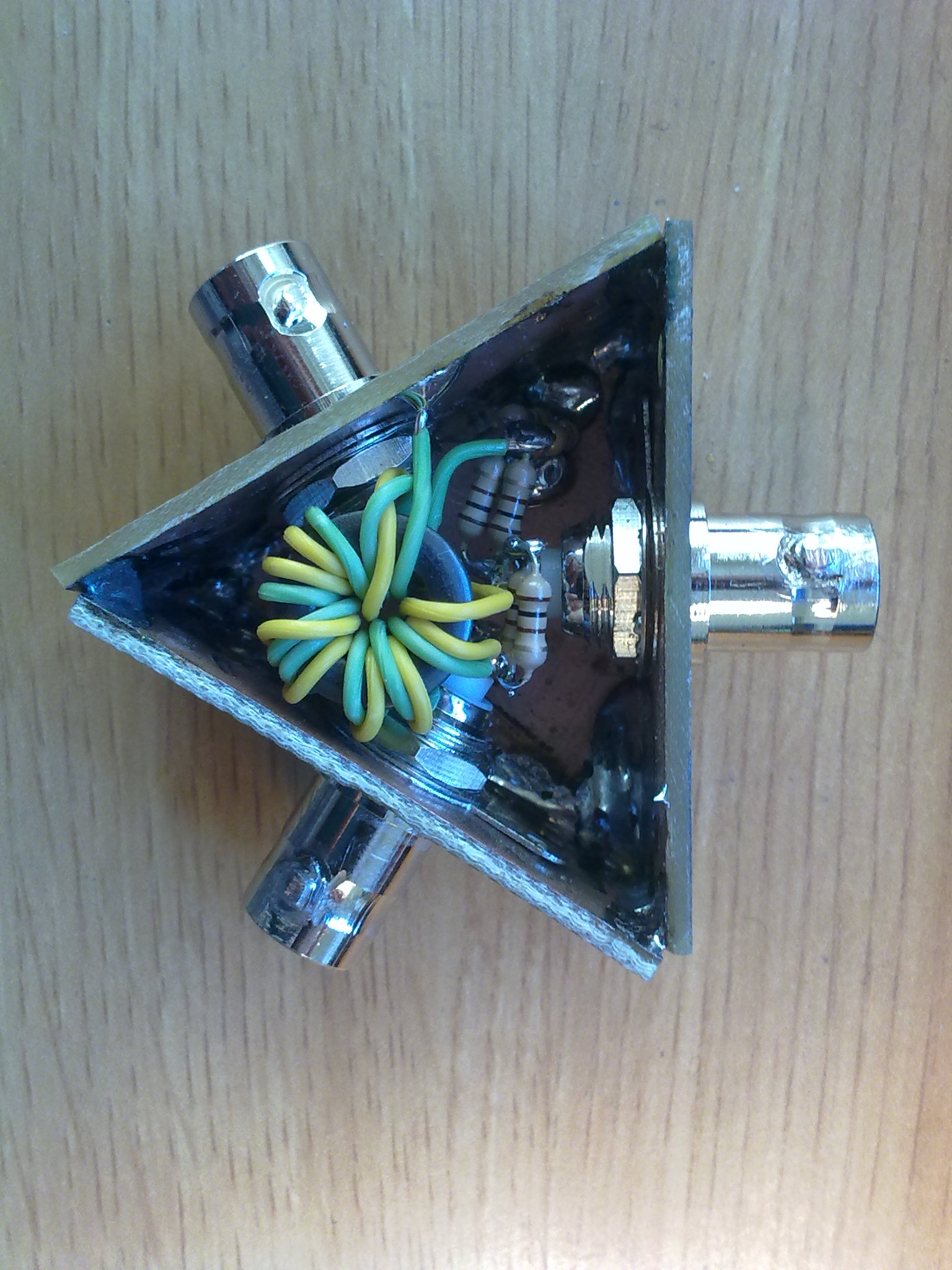 FIGURE7:-6 dB HYBRID COMBINER
|
For this measurement we only need one generator.
Switch off AGC. My home made receiver do not have AGC, the comercial units do have, of course.
Receiver audio output level is set at half way volume. Receiver output signal is fed into sound card input with coaxial audio cable. Sound card level is set so there is a good level at the Linrad waterfall. We should ensure that there is no distorsion in the sound card. We let some dB of margin before sound card saturates.
Set signal generator level at -85 dBm, or just anylevel that will produce a big signal on the receiver. Tune the receiver and find the signal into the waterfall. Tune frecuency to have an audio tone at the receiver passband center. I like 1 kHz tone.
Set Linrad filter BW at 500 Hz. Configure Linrad Smeter to show comfortably dB units. Adjust the scale to easily see 1 dB increments.
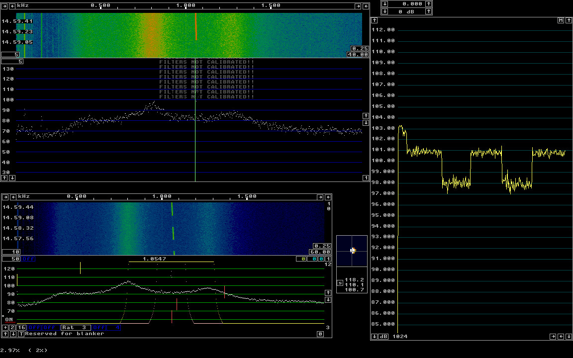
Switch the generator off. Take note of noise level in dB, this is the noise power level. Switch generator on. Adjust generator level with the step attenuator until you see an audio level increment of 3 dB. This is the signal plus noise level.
Now we have:
MDS(dBm)=GENERATORLEVEL(dBm)-STEPATTLEVEL(dB)
For this measurement we need both generators, the hybrid combiner and step attenuator. Connect both generator to hybrid coupler inputs. Connect the hybrid ouput to the step attenuator input. Connect the step attenuator ouput to the RX input. Tune the first generator on F1=7.000 kHz and the second one on 7.020 kHz
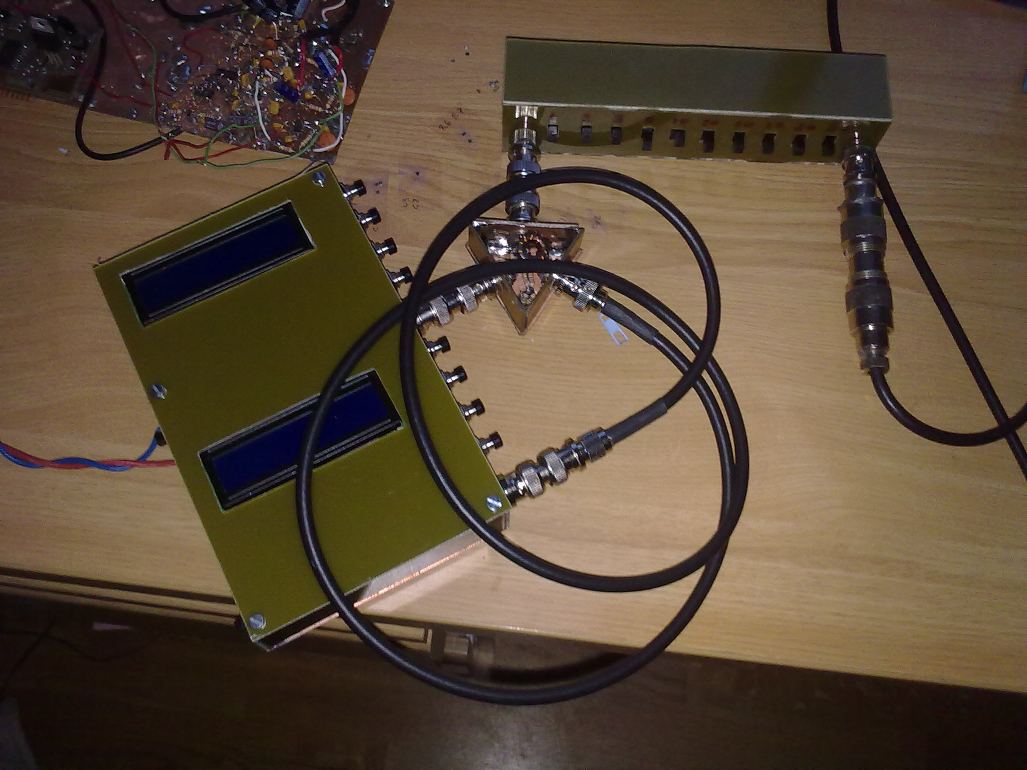
My DDS signal generators have an output level of -8.4 dBm. There is a 6 dB loss in the hybrid, so signal level is -14.4 dBm for each tone after the hybrid.
The measerument is the same as for MDS, but we are going to measure at the third order product 7.040 kHz. So we must tune the receiver on that frequency and search for the IMD tone. You sould inject enough two tone RF level into the receiver for the IMD tone to rise over the noise. The better the receiver is, the higher tones we need. You must play with step attenuator until you get a IMD tone that "emerges" 3 dB over the receiver noise floor.
GENIMDLEVEL=GENERATORLEVEL(dBm)-HYBRIDATT(dB)-STEPATTLEVEL(dB)
So we have found the signal generator level GENIMDLEVEL(dBm) for each tone that generates an IMD product that has the same power as the receiver noise floor at 500 Hz bandwidth. We are ready for getting SFDR value:
SFDR(dB)=GENIMDLEVEL(dBm)-MDS(dBm)
Here we have a Linrad screen capture example of the measurement session, showing a 3 dB (S+N/N) ratio (a bit lower)
The following measurements were done on the receivers I have at my radio shack:
| RECEIVER | MDS(dBm) | SFDR(dB) |
| QRP 7 MHZ original state | -136 | 78 |
| QRP 7 MHZ with 10 dB att between preamp and mixer | -136 | 83 |
| Elecraft K3, PREAMP ON | -138 | 101 |
| Yaesu FT-897 IPO OFF | -136 | 95 |
| Yaesu FT-897 IPO ON | -131 | 97 |
| Yaesu FT-817 IPO OFF | -135 | 82 |
| Yaesu FT-817 IPO ON | -130 | 86 |
Results are close to what is published here:
Receiver comparison tableExcept for FT-897 SFDR values that differ too much. I have to investigate the cause of such deviation.
- Improve DDS generator output return loss over the HF range. That would imply a better adjustment of the low pass filter.
- Place some attenuators between generators and the hybrid coupler to improve 50 ohms match.
Experimental Methods In RF Design. ARRL. Wes Hayward, W7ZOI, Rick Campbell, KK7B, and Bob Larkin, W7PUA
The Intercept Point. (IP3). Leif Asbrink, SM5BSZ
Receiver Dynamic Range. Leif Asbrink, SM5BSZ
  Copyright (c)  2013 Ramiro Aceves .
  Permission is granted to copy, distribute and/or modify this document
  under the terms of the GNU Free Documentation License, Version 1.2
  or any later version published by the Free Software Foundation;
  with no Invariant Sections, no Front-Cover Texts, and no Back-Cover
  Texts.  A copy of the license is included in the section entitled "GNU
  Free Documentation License".