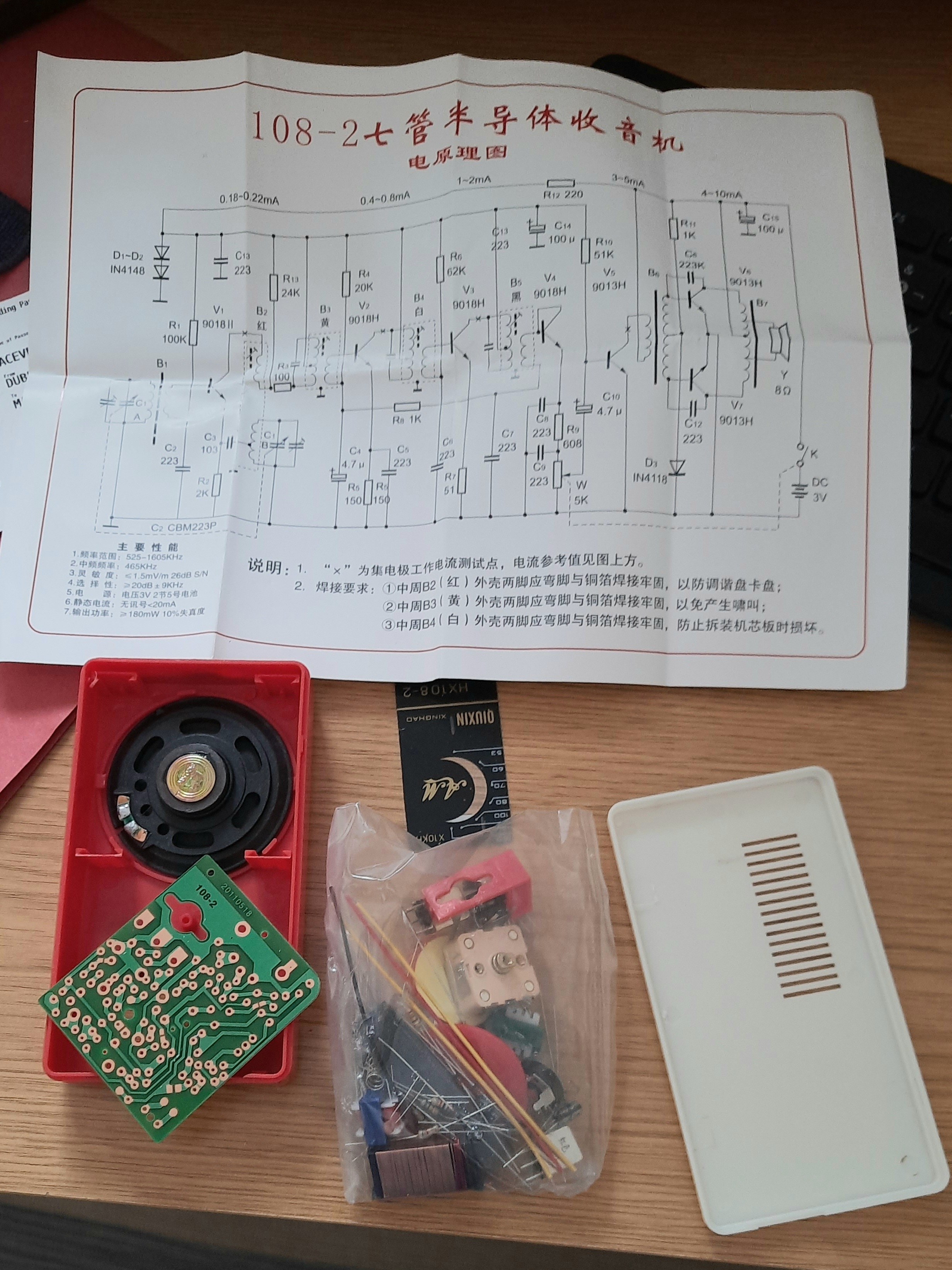
I was curious about the inexpensive, traditional transistor medium-wave receiver kits sold on AliExpress. I discovered the HX108-2 kit, placed an order, and received it in just over seven days.
The kit came with two single-sheet instruction manual, which are not very suitable for inexperienced builders. The presence of Chinese characters also makes the assembly process less straightforward.
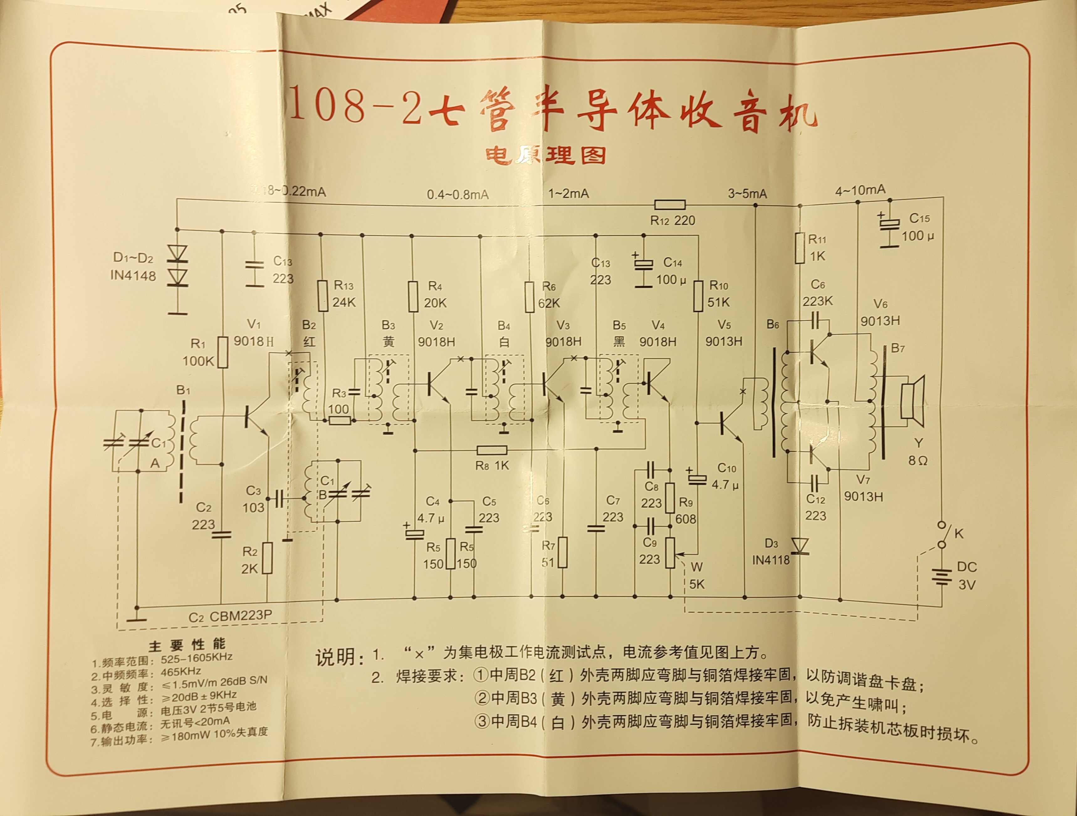
Before doing anything, I studied the circuit and searched for information about the receiver on the internet.
I found two excellent pages and strongly recommend reading them before attempting to assemble the receiver.
https://leap.tardate.com/radio/am/hx108-2/
https://hb1bbs.com/HX108-2-AM-Receiver/
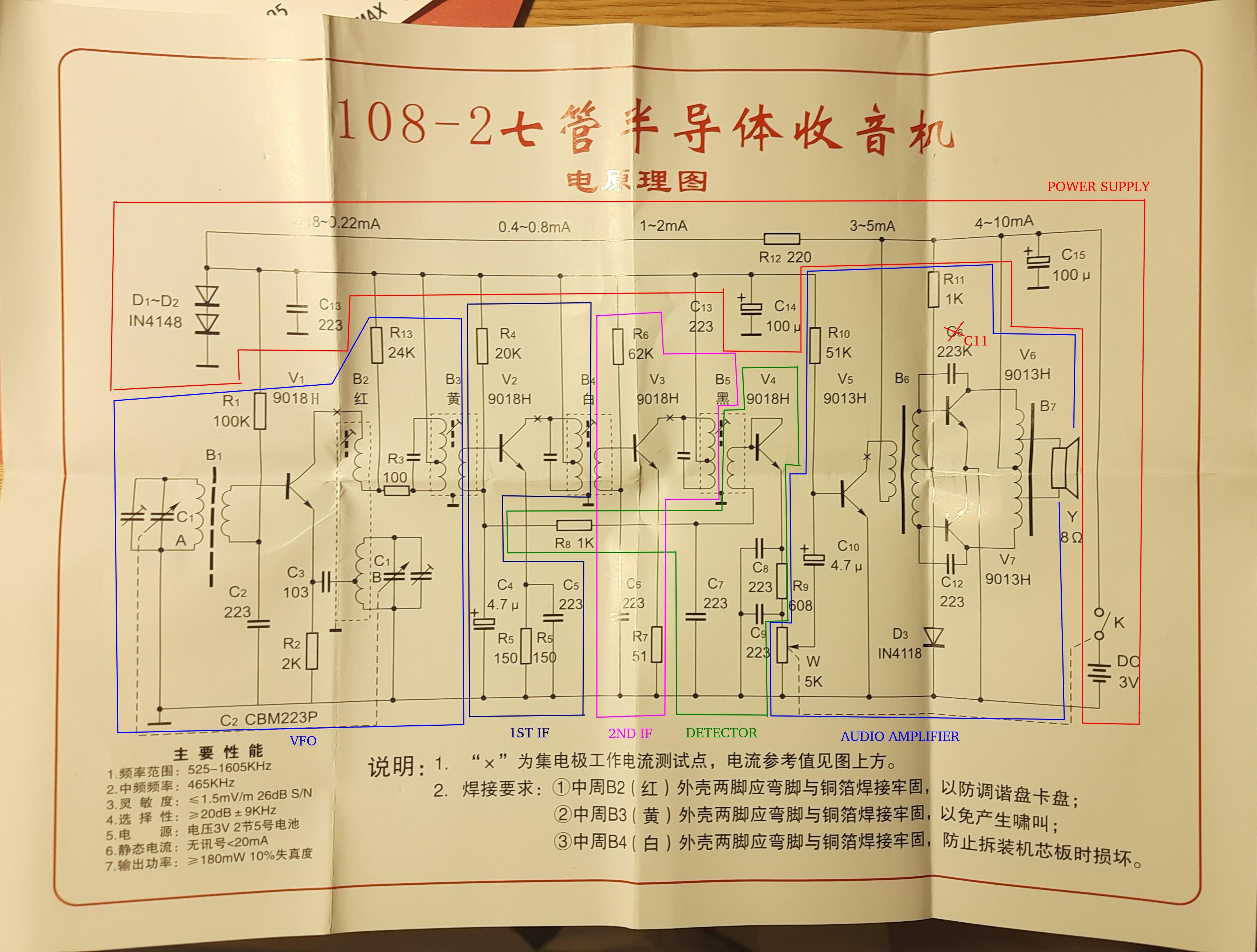
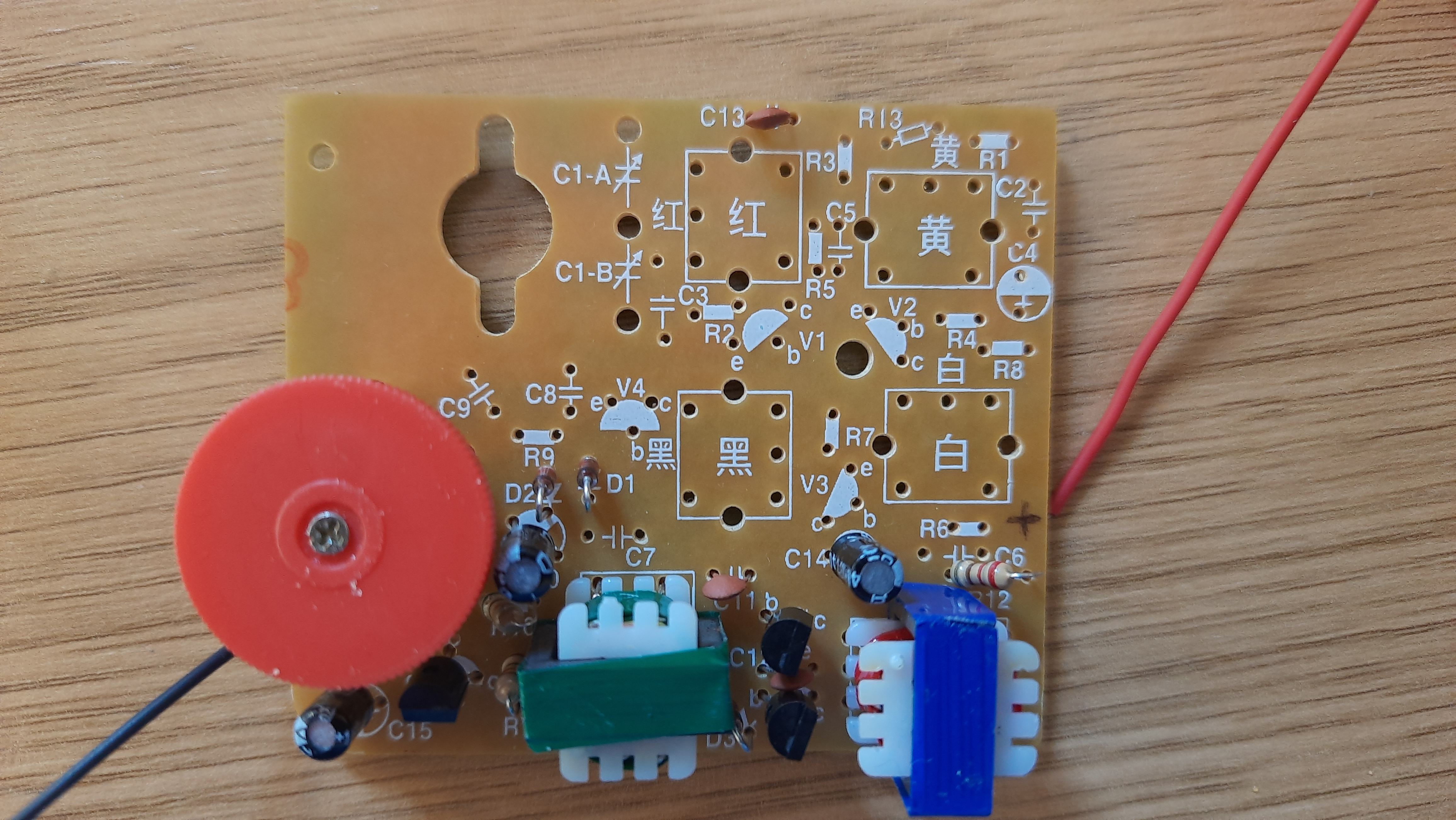
Here you can see receiver stages, from left to right:
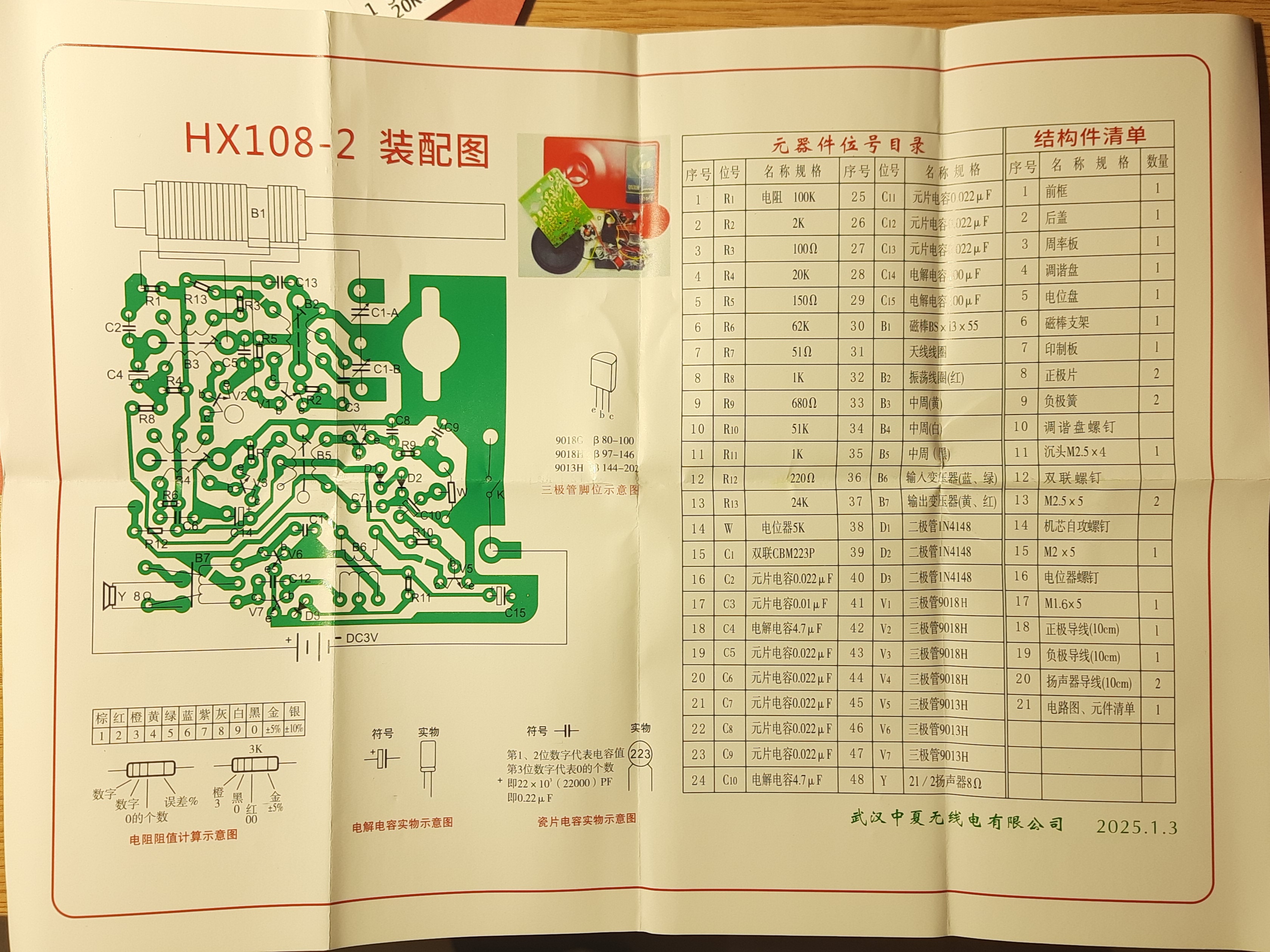
To ensure a safe and reliable assembly, I measured every component before soldering it in place. This was a bit annoying, but it helped me to confirm that each part was functional and that I hadn’t made any mistakes when selecting components. I checked every resistor, capacitor, and transformer winding.
I didn’t have enough patience to measure the RF transformer with a VNA, and I also couldn’t measure the BJT transistors’ beta, since I didn’t yet have the inexpensive test equipment that I ended up ordering from AliExpress a few days later. Instead, I measured V_BC and V_BE junction voltage drops using a simple tester.
K switch nominal: 0 Ohm measured: 0.25 Ohm C15 capacitor nominal: 100uF measured: 132 uF R12 resistor nominal: 220 Ohm measured: 215 Ohm D1 diode IN4148 Vf: 0.602V D2 diode IN4148 Vf: 0.608 V C13 capacitor nominal: 22 nF measured: 21.6 nF C14 capacitor nominal: 100uF measured: 132 uF
Speaker nominal 8 Ohm measured: 7.37Ohm B7 output transformer 1.97: 1.6+1.6 Ohm (RED) R11 nominal: 1K measured: 968 Ohm D3 diode IN4148 Vf: 0,603V C6 C11 capacitor nominal: 22 nF measured: 21.87nF C12 capacitor nominal: 22 nF measured: 21.28 nF V6 transistor 9013H Vbc: 0.72V Vbe:0.72 V V7 transistor 9013H Vbc: 0.72V Vbe: 0.72V B6 input transformer 164 : 71+71 Ohm (GREEN) R10 resistor nominal: 51kOhm measured: 50.45Ohm V5 transistor 9013H Vbc: 0.72V Vbe: 0.72 V C10 capacitor nominal: 4.7uF measured: 5.3uF W volume pot 5K, measured 4.380k. V5 current:3.39mA V6-V7 current:3.93mA Total: 17 mA
V4  transistor 9018H Vbc: 0.787V Vbe: 0.793V
C8 capacitor nominal: 22 nF measured: 23.3 nF
R9 nominal608 680 Ohm measured: 672 Ohm
C9 capacitor nominal: 22 nF measured: 21.05 nF
R8 nominal 1KOhm measured: 984 Ohm
C7 capacitor nominal: 22 nF measured: 23.6nF
B5 transformer BLACK
R6 nominal 62KOhm measured: 61.93kOhm
V3  transistor 9018H Vbc: 0.78V Vbe: 0.79 V
R7 nominal 51Ohm measured: 49.9 Ohm
C6 capacitor nominal: 22 nF measured: 24.38 nF
B4 transformer WHITE
R4 nominal 20kOhm measured: 19.58 Ohm
V2  transistor 9018H Vbc: 0.787 V Vbe:0.793 V
C4 capacitor nominal: 4.7uF measured: 5.12 uF
R5 nominal 150Ohm measured: 145.1 Ohm
C5 capacitor nominal: 22 nF measured: 19.86nF
B3 transformer YELLOW
R13 nominal 24 kOhm measured: 23.13 Ohm
R3 nominal 100 Ohm measured: 97.8Ohm
C1 var tuning capacitor
159-12.8 pF
75-14.4 pF
B2 transformer RED
C3 capacitor nominal: 10 nF measured:14.8 nF
C2 capacitor nominal: 22 nF measured: 23.2 nF
R1 nominal 100 kOhm measured: 100.2Ohm
R2 nominal 2 kOhm measured: 1.97kOhm
V1  transistor 9018H Vbc: 0.788V Vbe: 0.794V
B1 ferrite  bar antenna
555uH-7,83uH


First, audio stage was assembled and tested using a 1 kHz tone from the signal generator. Audio was loud and clear.
A 465 kHz 1 kHz AM modulated RF signal was generated using a UNIT-T UTG962 Waveform Generator. B3, B4 and B5 transformer adjusting rods where tuned to maximum audio on the speaker.
A 1000 kHz 1 kHz AM modulated RF signal was generated, C1 main tunning capacitor in combination with B2 transformer were adjusted until an audio tone was clearly heard at the speaker and C1 was at mid range position.
Then on the air signals were clearly heard and could be used for fine tune the IF transformers to maximum output and the C1/B2 VFO frequency to match dial indication.
Radio was quite sensitive and could easily tune all 4 MW stations that remained active on the air in Madrid at that moment. Saddly, RNE1 and RNE5 stations closed for ever on 2025-12-30 at 03:00 EA time. Now there are only two stations to enjoy this receiver.
ÚLTIMA EMISIÓN RNE1 MADRID EN 585 kHz
RADIO MADRID (CADENA SER) 810kHz CIERRA EMISIONES EN ONDA MEDIA EN MADRID
No sound: 17 mA
Quiet room normal station listening: 23mA avg
Full power: 200mA
V1 e= 0,59 b=1,16 c=1,33 V
V2 e= 0,040 b=0.770 c=1,36 V
V3 e= 0,078 b=0,789 c=1,36V
V4 e=0.145  b=0.734 c=0.730V
V5 e= 0.007 b=0.644 c=2,46V
V6 e= 0.005 b=0.632 c=2.99V
V7 e= 0.005 b=0.632 c=2.99V
  Copyright (c)  2013 Ramiro Aceves .
  Permission is granted to copy, distribute and/or modify this document
  under the terms of the GNU Free Documentation License, Version 1.2
  or any later version published by the Free Software Foundation;
  with no Invariant Sections, no Front-Cover Texts, and no Back-Cover
  Texts.  A copy of the license is included in the section entitled "GNU
  Free Documentation License".