In a past article, Simple SDR HF receiver design, I described the fascinating adventure of reinventing the wheel of cheap SDR receivers. A working prototype was built with good results. I learnt a lot of things with it.
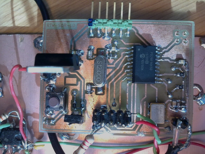
The heart of that receiver was what I called the RTW-SDR-LOCALOSC PCB board. The hardware design was very simple. The CPU is a Microchip 18F14k50 20 pin SOIC microcontroller running from a 12 MHz crystal. It has ICSP (In Circuit Serial Programming) for updating the code, USB port and clock working frequency of 48 MHz. The signal generator is the famous Si-570 chip from SILABS. The Si-570 chip has got I2C serial interface for frequency programming and LVDS diferential outputs. Maximum frecuency range specification is 10-280 MHz, but people confirm good behaviour at frequencies as low as 3.5 MHz). I provided a 10 pin output connector to control the filter board switching relays. Those connector pins may be used for any input or output as desired in future experiments, receivers, transmitters, and so on..
Frequency control was done by
pressing two microswitch buttons. Also It will be able to be programmed by the USB connector, a feature that is not working yet.
It was the right moment to add a rotary encoder to this board to have a more useful and professional look.
The home made board looked like this:
I redesigned the board and corrected a few previous mistakes using free software KICAD. The board is powered from the USB BUS to avoid using external power supplies. It can be powered from a 5V power supply if desired. Both LVDS outputs are available. It has a RESET button and can be externally programmed through the ICSP connector (I use a PICKIT2 USB programmer from Microchip). The final schematic looks like this:

I sent the board files to OSHPARK and after two weeks I received three beautiful PCB boards for 12 €. That was great!


I ordered a new SI-570 chip from SDRKITS. The thing on the top is not a soldering iron, is a ball-point pen tip! :-):


The board worked as expected. I could change frequency by pressing the up and down buttons as before. But I would like to add a rotary dial to the board in order to change frequency by rotating a wheel.
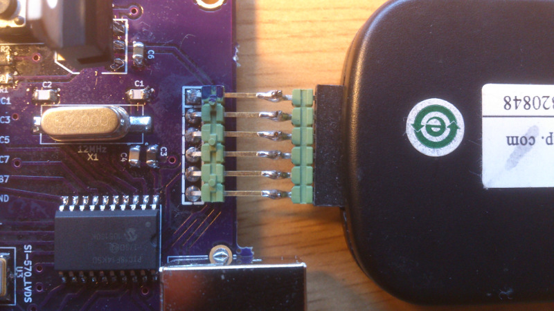
I bought a 12 pulses/12 detents rotary mechanical encoder from ALPS. The model was EC12. I arranged it this way:


Rotary encoder pins were connected to RB5 and RB7 input pins of the microcontroller. A filter was used to reduce the chance of contact bouncing and chattering. The signals from the encoder are two waves 90 degree out of phase. If we move the encoder to the right, A signal is before B signal. If we do it to the left, B signal is before A signal.

Interrupt is an event that occurs at any time during program execution. When that happens, program counter jumps to ISR, the Interrupt Service Routine. Once we do the things we want, the program execution comes back and continues at the point in wich it was interrupted.
PIC18F family of microcontrollers have various kinds of possible interrupt sources. For getting the encoder work, we are going to use the IOCB interrupts, Interrupt On Change on Port B, that is, an interrupt that happens when there is an input pin level change at PORT B.
Programming algoritm is very simple:
Determining the right amount of time needed to wait for a stable signal was easy. The manufacturer states that any bouncing or chattering should occur during less than 3 ms.
The oscilloscope is an useful tool. Here we can see the traces of both encoder output channels:

If we take a closer look, we can see this garbage on some traces:

I have recorded dozens of pictures and checked that signal is stable after 2 ms. But in order to agree with the manufacturer and to be in the safe side, we will wait at least 3 ms before reading the value at RB7 pin.
Programming the interrupt routine is easy when you see a ready made program, but when you are a novice as I am, getting things working takes some time and try and error sequences.... :-)
First, we need to tell the PIC that RB7 and RB5 are inputs setting up the bits 7th and 5th at PORTB tristate register TRISB:
TRISB=0b11110000;/*RB6=SCL, RB4=SDA, RB7=RB5=INPUTs*/
We disable weak pullups in RB7 and RB5, we do not need them because we are using fisical pullup 10k resistors.I had previously enabled them for the up and down buttons used in the SDR prototipe. I disable them now with the 7th bit of INITCON2 register
WPUB= 0b10100000;/*RB7, RB5, WEAK PULLUP ENABLED*/>
INTCON2=0b11110101; /*DISABLE PULLUPS<
Now we enable PORTA and PORTB interupts:
RABIE=1;
We enable the Interrupt On Change Interrupt on PORT B, pin RB7:
IOCB7=1;
We tell the SI-570 to be programmed with the starting frequency (in example, 14 MHz), enable the interrupts and enter in an endless loop that will be interrupted somewere anytime:
prog_si570 (FRECUENCIA);

GIE=1; /*GLOBAL INTERRUPT ENABLE*/


while(1){ /*ENDLESS LOOP WAITING FOR AN INTERRUPT TO OCCUR*/


        }
Here we have the code of the ISR routine:
void interrupt pulsaboton(void){

    Delay1KTCYx(40    );
     if (RABIE && RABIF && PORTBbits.RB7==1 && PORTBbits.RB5==0){

         FRECUENCIA=FRECUENCIA+DELTA;
                prog_si570 (FRECUENCIA);
                char x=PORTBbits.RB7;
                RABIF=0;
                return;
        }

      if (RABIE && RABIF && PORTBbits.RB7==0 && PORTBbits.RB5==0){

          FRECUENCIA=FRECUENCIA-DELTA;
               prog_si570 (FRECUENCIA);
               char x=PORTBbits.RB7;
               RABIF=0;
               return;
      }

    char x=PORTBbits.RB7;
    RABIF=0;
    return;
}
Processor cycle time is 4/Foscillator. For a 48 MHz clock, we have Tcyle=4/48e6=83.33ns
We will wait for a period of 40.000 Tcyles, so, the time will be 3.33 ms.
We check first if PORTA/B interrupts were enabled and if an interrupt on pin change of PORTA/B occurred, that is, if the RABIE & RABIF flag bit were set.
Once we know if the encoder movement was rightside or leftside, we increment or decrement the programmed frequency, disable interrupt flag and return from the interrupt to the main program.
IMPORTANT: the following two actions must be done after we service the interrupt. Not doing it can lead to very strange microcontroller behaviour:
I forgot to do the first one and I had an erratical encoder behaviour. The reason of this is that RABIF bit is set when the value of PORTB input pin differs from the last read value. Once the interrupt is attended, forcing a read at PORTB clears de mismatch condition. Forgetting to do so triggers a new interrupt as soon as we abandon the ISR routine. This can be understood by taking a look to the schematic of an input pin. I borrowed it from PIC16F84 datasheet. PIC18F14K50 datasheet did not include this great explanatory picture.

The full microcontroller C code can be downloaded here, included all SI-570 programming routines:
si570-vfo-encoder.cNow we have a working oscillator that can be tuned using a rotary dial. We will extend its functionality with aditional buttons to change the frequency increments to be added or substracted from the current frequency. We will add an LCD display to show the frequency and other things. Many things to do and improve in the future.
  Copyright (c)  2013 Ramiro Aceves .
  Permission is granted to copy, distribute and/or modify this document
  under the terms of the GNU Free Documentation License, Version 1.2
  or any later version published by the Free Software Foundation;
  with no Invariant Sections, no Front-Cover Texts, and no Back-Cover
  Texts.  A copy of the license is included in the section entitled "GNU
  Free Documentation License".