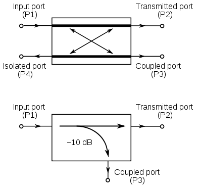
Directional couplers are 4 port devices that are very useful for making RF measurements. Although they can be bought at Ebay for reasonable prices, I was just curious about making them myself for 1296 MHz amateur radio band.
One interesting type of directional coupler is the microstrip directional coupler, it can be built using 2 layer printed circuit board (PCB). Directional couplers have input, transmitted, coupled and isolated ports. It is built using two transmission lines close each other, so that energy that passes from input to transmitted port is coupled to the coupled-isolated port. At coupled port we have a sample of forward wave from the signal generator. At isolated port we have a sample of the reflected wave from the load.

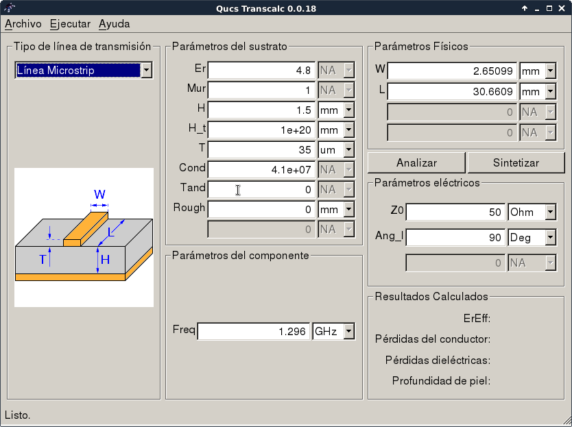
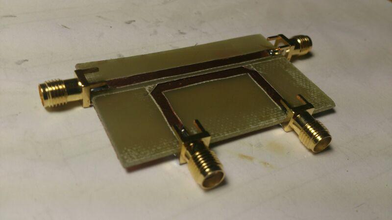
A friend of mine, Miguel, EA4EOZ told me that microstrip lines could be built easily using a cutter and applying heat with the soldering iron. I built a quick directional coupler without thinking too much about line lenghts and their separation. The only thing I tried to do well was line width, it was calculated using QUCS transmission line software:
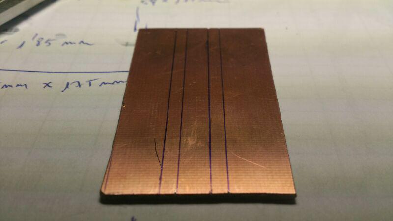
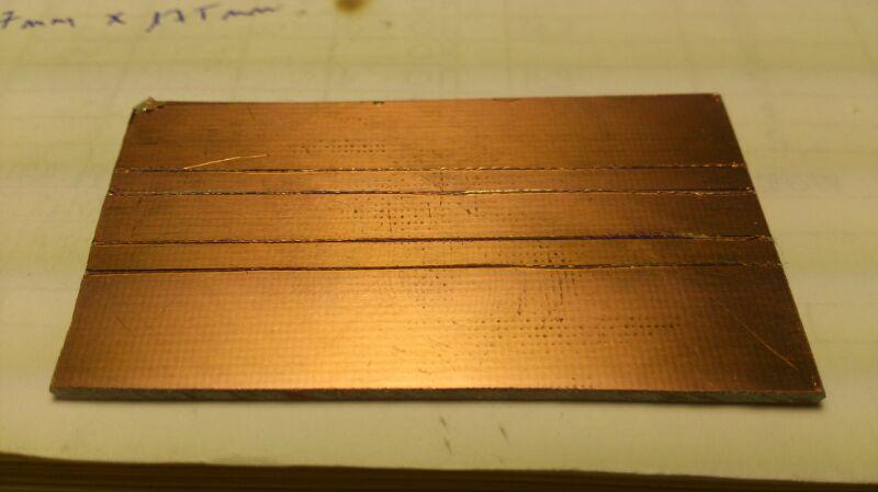
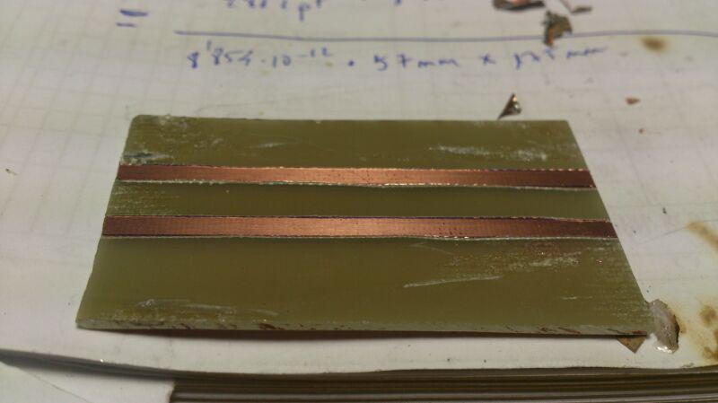
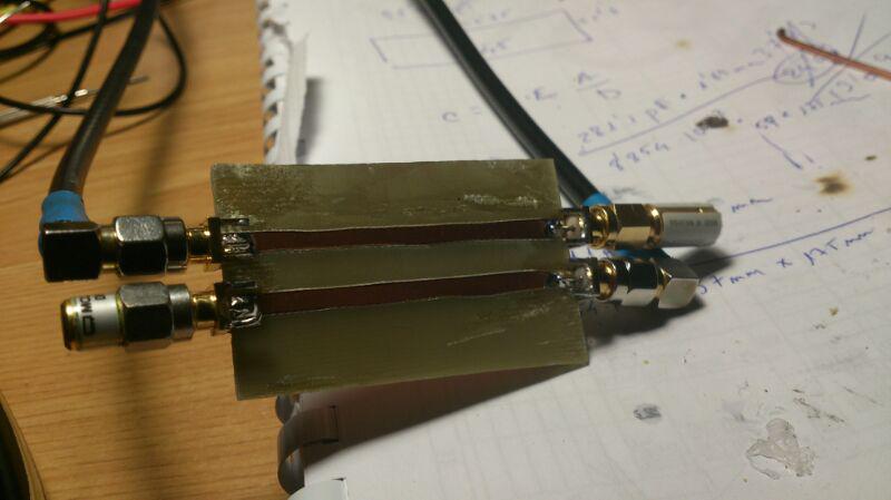
The coupler was measured at 1296 MHz using a VNWA3 vector network analyzer and checked against my Marconi 6200 microwave test set, getting similar results. Coupling was -37.65 dB. Return loss at the input was -19.3 dB. Well, not too bad for the first attempt. I measured at the isolated port and horrorrr, I got less attenuation at isolated port than at coupled port. It was clear that I needed to study the subject before continuing.
After reading several microwave book chapters about directional couplers, I learnt some important things:
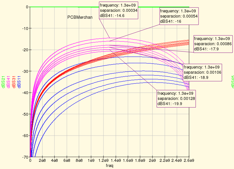
I played with QUCS software for a while to see how all the variables take into account
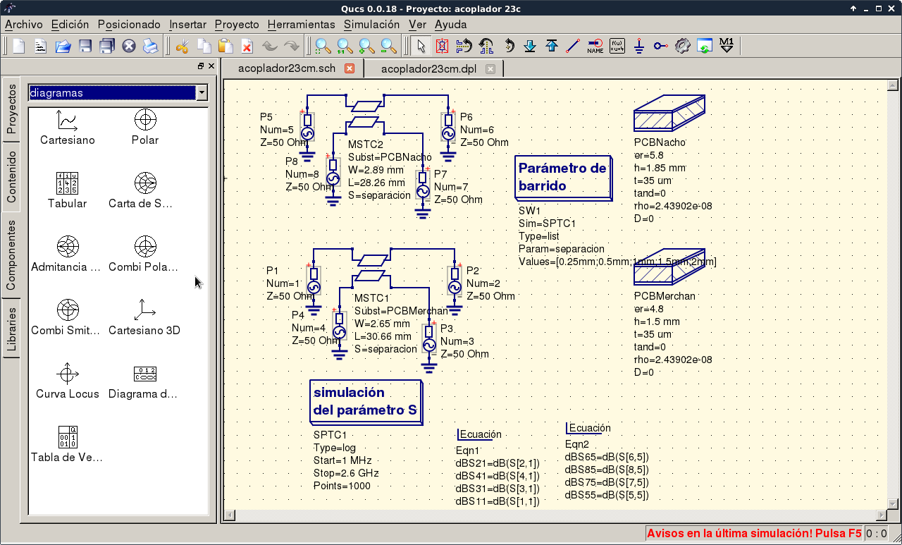
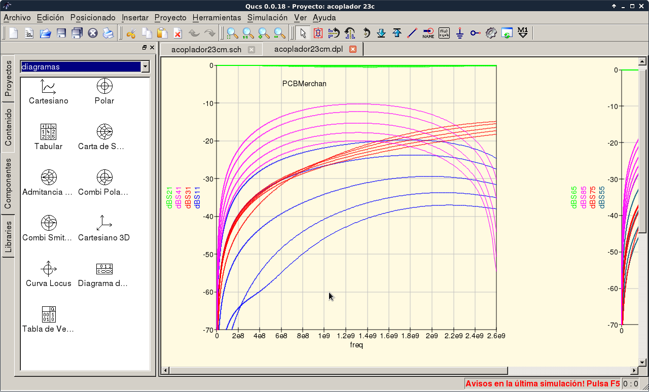
After simulation work I was ready to build another quick and dirty directional coupler:
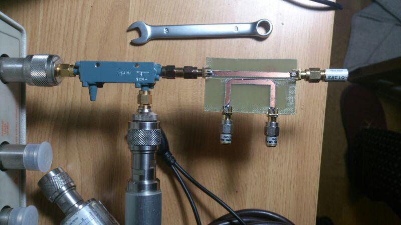
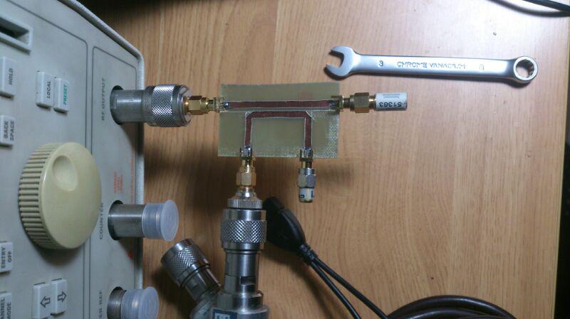
The measurement results were the following:

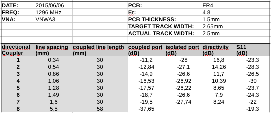
Directivity was not good but at least we have it!
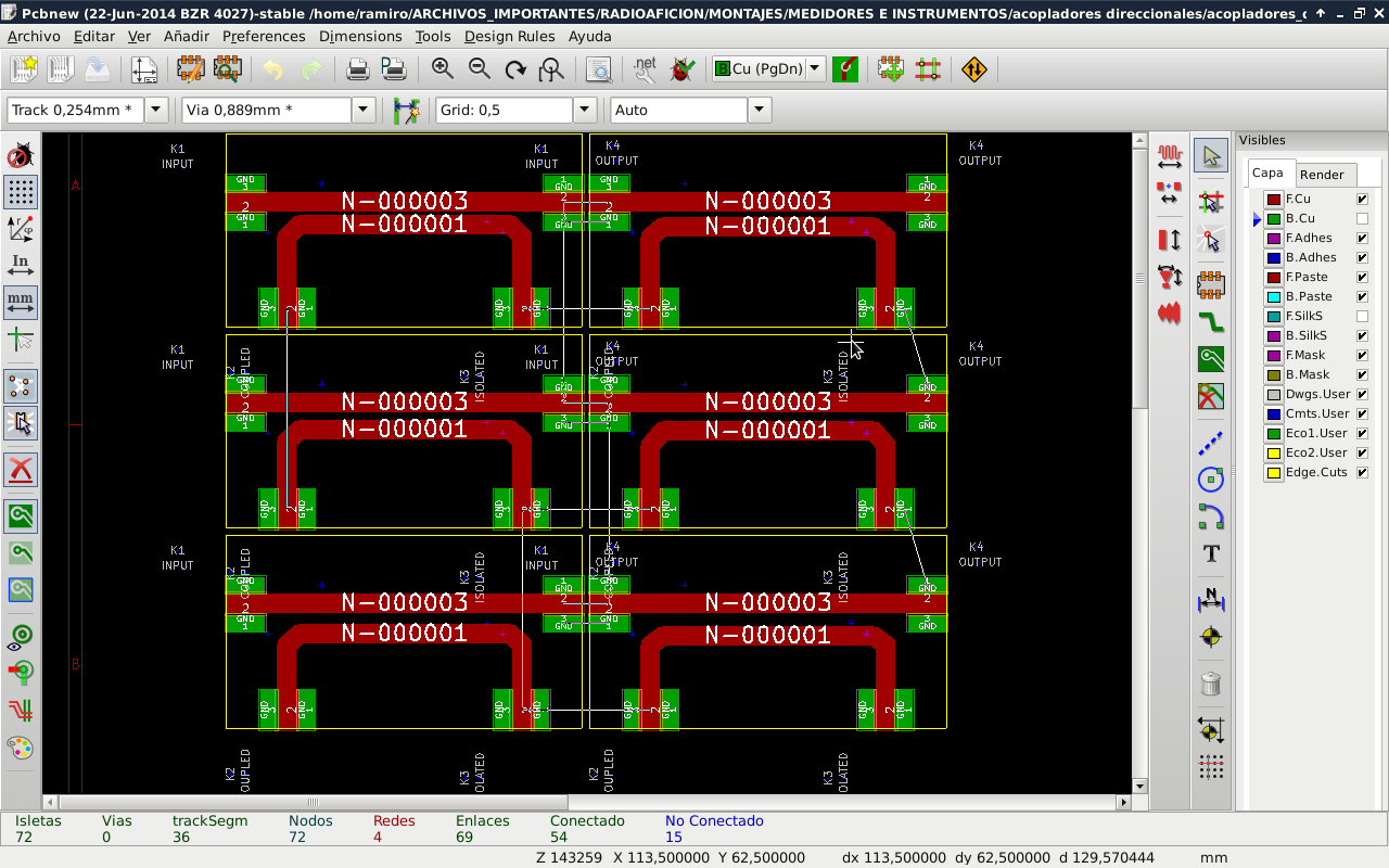
I designed a new directional coupler using KICAD free software.
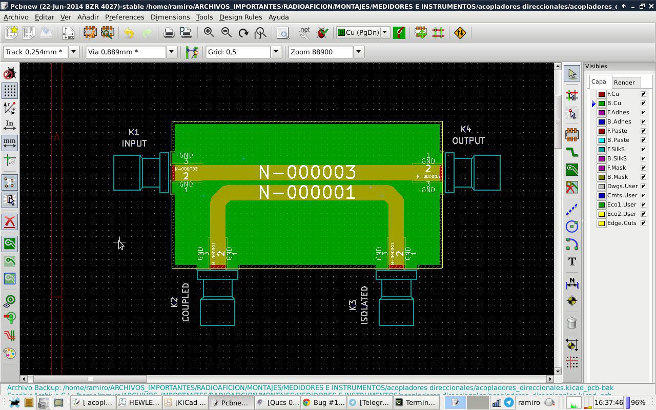
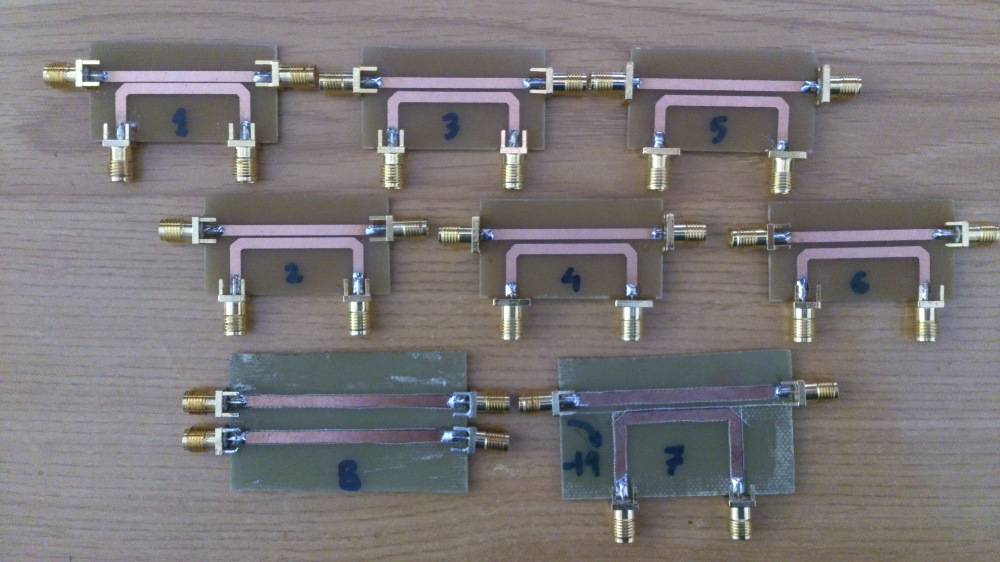
I copied the design 6 times to get 6 directional couplers with different line spacings: 0.25, 0.5, 0.75, 1, 1.25 and 1.5 mm.
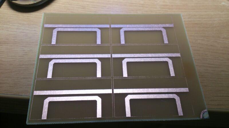
With the aid of my home made light box and the usual PCB etching techniques, I got this 2 layer PCB:
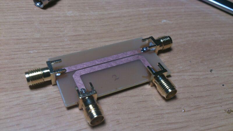
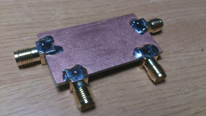
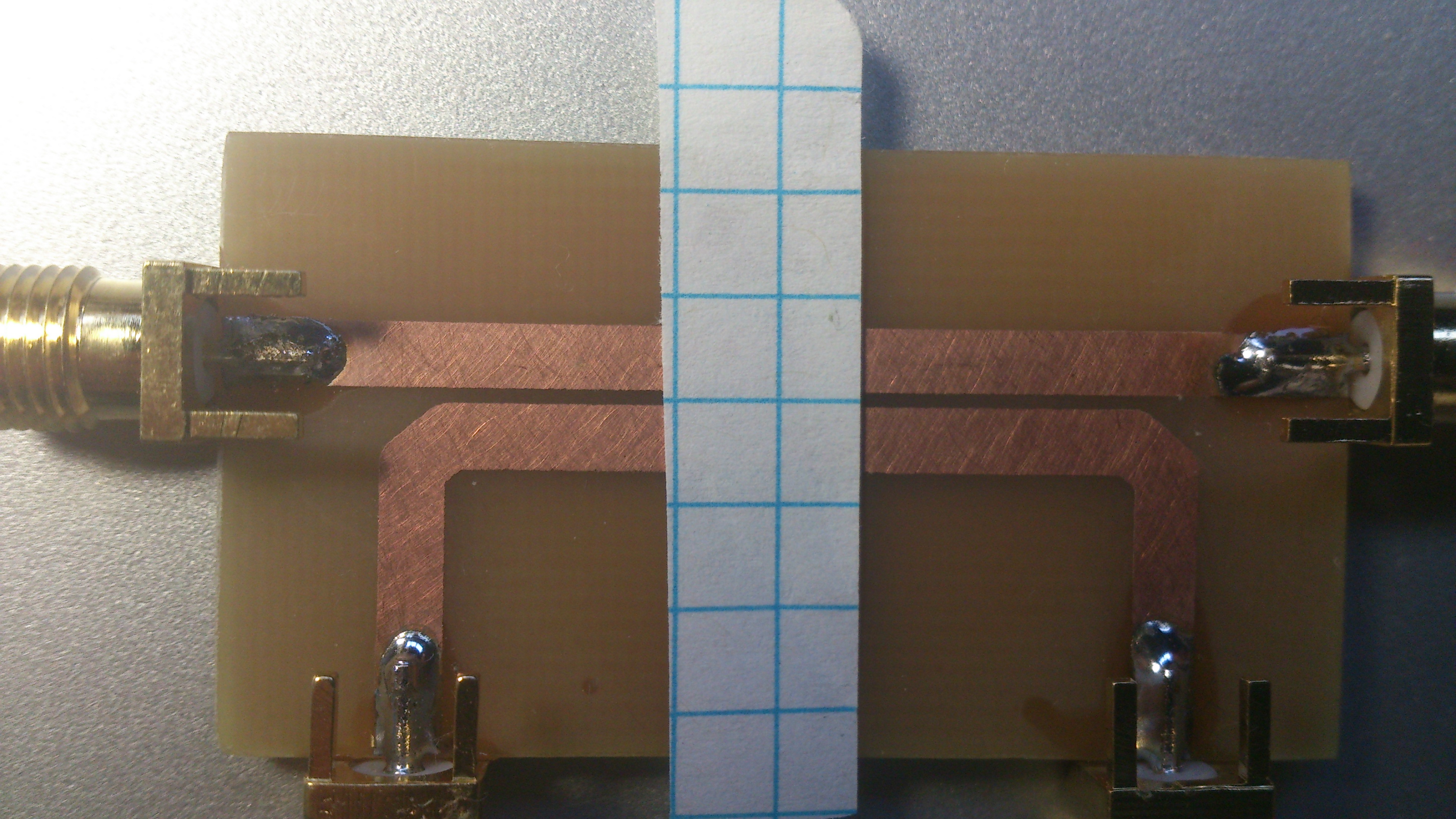
My friend Ricardo, EA1RJ suggested this simple method to measure actual stripline separation. After taking the photo, the distances where measured using measuring tool in GIMP software.
Measurement results are shown in the next table:
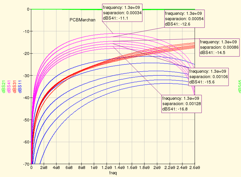
Measured coupling values are not too far from the QUCS calculated values using Kirschning coupled line model. Hammerstad model predicts higher values instead:
Strip line couplers for 1296 MHz band are easy to build using a home made light box but with some limitations. They can be used for forward power measurement with no special problems, provided that you measure them first and know the coupling coefficient . On the other side, directivity is rather poor. The closer the lines, the better directivity you obtain. So if you want high directivity you need very close spaced lines, getting high coupling. That is a problem for measuring return loss at high power. You can get arcs between the lines and also you will have to dissipate the excess of coupled power using a high power attenuator.
Microwave Engineering. D. M. Pozar
Microwave Engineering Using Microstrip Circuits. E. H. Fooks and R. A. Zakarevicius
Microwave Solid State Circuit Design. Inder Bahl and Prakash Bhartia
  Copyright (c)  2013 Ramiro Aceves .
  Permission is granted to copy, distribute and/or modify this document
  under the terms of the GNU Free Documentation License, Version 1.2
  or any later version published by the Free Software Foundation;
  with no Invariant Sections, no Front-Cover Texts, and no Back-Cover
  Texts.  A copy of the license is included in the section entitled "GNU
  Free Documentation License".