
Every radio ham needs an SWR meter. Even though comercial rigs have builtin digital readout SWR meters, having an external one is a good idea. I own three comercial radios (of course with built in SWR meters), but also have a bunch of beloved home made QRP rigs, a T match tuner and 40m long windom dipole. I needed an external SWR meter in order to match the antenna into such rigs. In this breaf article I want to show you the problems I found building my SWR meter.
Looking for SWR meter schematics, I found a simple one in the RSGB Radio Handbook. The schematic looked like this:
I had a terrible misunderstanding about how an SWR meter works. I always believed that the sensing toroid used by those meters had some kind of black magic to separate forward and reflected waves (please see bibliography at the botton of this page, G3YNH WEB page explains this). That is an absolutely non sense. Inside a transmision line that is terminated into an impedance different to its characteristic impedance, there are forward and reflected waves. But if we do not use such line, only a load, there are no travelling waves. There are no standing waves. SWR meters work by sensing the voltage and current at the point that are connected. Anything else. If we convert the current into another voltage, and we add and substract both voltages, we have the reflected and forward voltage indication.
Current sensing device is a 1:12 turns transformer on a FT-50-43 ferrite toroid. Primary winding has one turn, secondary 12 turns. Secondary current is thus reduced times 12 and transformed into a voltage by flowing across the resistors R3/R4. Literature calls that voltage "Vi" cause it is a voltage derived from the current on the line.
Voltage sensor is a resistor divider R7/R8. We will name the voltage at R8 "Vv", cause it is a voltage derived from the voltage on the line.
Reflected power is proportional to the square of |Vv-Vi| and direct power is proportional to |Vv+Vi|. Two BAT 42 schottky diodes are used as rectifiers to drive the DC 50 uA panel meters. The bridge is adjusted so that |Vv-Vi|=0 when a 50 ohms dummy load is connected to the right side connector
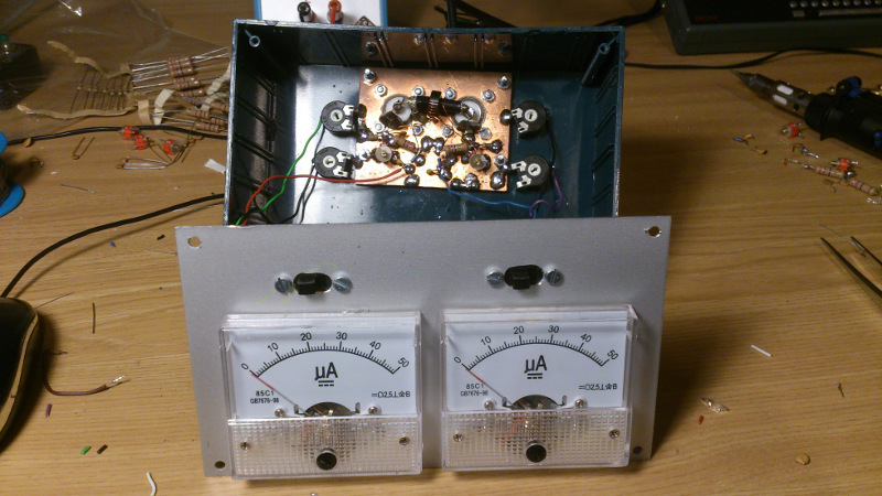
I got several cheap 50 uA panel meters on Ebay. 4 € each.... not too bad!
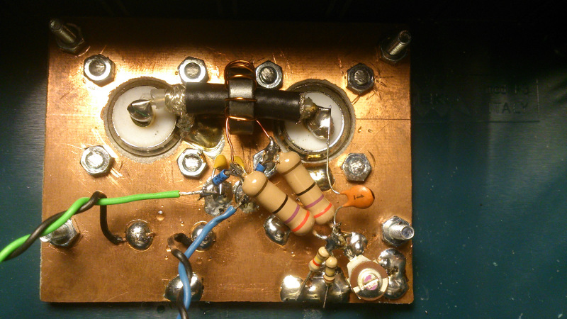
I built the circuit using the good ugly construction technique over a copper PCB. In the following pictures you can see the building procedure. Coaxial braid is grounded at TX side only. This acts as a faraday shield in order to prevent capacitive coupling to the toroid winding.

A potentiometer is placed at R8 to get a null reading at reflected voltage port with a 50 ohm dummy load.
Another two potentiometers are placed in series with the panel meters to adjust the full scale reading at the forward meter. They cannot be seen on the pictures cause they were soldered directly into the panel meters (in this first version, finally they were mounted into the PCB).


At first glance the circuit appeared to work, but as soon as I played with it a few minutes from 1.8 to 50 MHz, I noticed a poor null indication at 28 MHz and up frequencies. At high frequencies SWR readings were fake and compared to the internal rigs SWR meters were completely wrong. If I got a SWR null with my tuner, it ended being a true high SWR. I suspected that resistors could be wounded instead of carbon, but my network analyzer showed good behaviour over the HF range. I also blamed the variable potentiometer cause I measured some little capacitance across its terminals. I changed the potentiometer to a fixed resistor of the same value obtaining the same result. There should be a reason for the bad SWR meter behaviour.
After some investigation reading the literature, the RSGB circuit turned to be completely uncompensated and uses a common voltage sampling network for forward and reflected measurements. The high-frequency error is dued to voltage sampling network inductance and transformer effective shunt capacitance. So this circuit will never work properly.
I surfed the WEB again and found this interesting page in which another kind of bridge could be found:
F1FRV, Dominique WEB PAGE
This design uses a capacitive voltage sampling network and a new part, the resistor R7.
The resistor R7 is what is called the compensating resistor. This resistor compensates for the transformer secondary reactance at low frequencies. At low frequencies secondary reactance is comparable to R3/R4 and produces a Vi voltage phase error. Full explanation for that can be read in G3YNH WEB page (see below). For good accuracy at the lower frequencies the reactance of the secondary winding should be at least 7 times the value of the resistors.
Dominique WEB page has an spreadsheet to calculate circuit values. I just changed the resistor divider and placed a capacitor divider instead. I also added a compensation resistor in parallel with C2.
The circuit worked with good balance at full 1.8-50 MHz range, but it worked fine only if one meter was connected to the circuit output. Forward power meter reading seemed to interact with the reflected power meter reading. I arrived to the conclusion that high impedance meters should be used to make it work. That would force me to use operational amplifiers to drive the panel meters. I wanted a no battery powered SWR meter, so it was not a feasible solution.
The explanation is that at balance, the reflected power bridge presents no load, but the forward power bridge presents a low impedance and loads the voltage sampling network. This ruins the balancing of the reflected power bridge.
After several emails with Dom, he pointed me to this marvellous page:
Dave's page is "the bible" of the RF bridges. Everything is there, well explained and mathematicaly demonstrated. After several emails with him, I could see that Dave is an expert in this subject. It is a pleasure to have persons with such kind of expertise among us!
The recommended bridge schematic is the following Douma bridge with two voltage sampling networks:

There are two secondaries, 6 turns each. By using two voltage sampling networks, the problem of voltage divider loading was solved and with the help of the compensation resistor I got a very good behaviour over the 1.8-50 MHz range.
Calculation of component values can be done with the following formulas:

C1/C2=2*12*50/54-1=21.22
C1=C2*21.22=3.3*21.22=70.026 pF
Rv=63.36e-6/(2*3.3e-12*12*50)=16 kohm.
N, Ri, c2, and toroid type values must be choosed for each application. For a full understanding please read G3YNH Web page below.
C2, the upper capacitor, gets more than 100 V peak across its terminals when the bridge is powered with 100W. Even worse when the bridge is loaded with a higher than 50 ohms load. I have built two little capacitors using double side copper PCB and measuring them with my network analizer. If you zoom on the images you will be able to see them.
Interesting to note that the bridge could be improved a bit more by placing two small inductors into the top of the voltage dividers to compensate for the capacitive loading into the 50 ohms line. The effect of this capacitors is small and the inductors have been omitted. Performance is good enough for an all around SWR meter.
The meter has 2 scales. 10W and 100W full scale reading. Four adjustable resistors were placed for full scale adjustment


In this article I have described the problems I encountered when assembling my own HF SWR meter. It shows the importance of choosing a good design from the begining.
I have omited any demonstration of the math formulas as everything can be found at G3YHN Web page.
  Copyright (c)  2013 Ramiro Aceves .
  Permission is granted to copy, distribute and/or modify this document
  under the terms of the GNU Free Documentation License, Version 1.2
  or any later version published by the Free Software Foundation;
  with no Invariant Sections, no Front-Cover Texts, and no Back-Cover
  Texts.  A copy of the license is included in the section entitled "GNU
  Free Documentation License".