In this page I will briefly describe the design of a simple but decent HF Software Defined Receiver, SDR. I am not going to invent anything, it is intended only as an own educational project to learn how things work and get in touch with SDR. SDR receivers of this kind are superceeded by modern RF direct sampling techniques, but they can offer good performance at low cost. A friend of mine is an expert DSP, PIC, everything programmer so I thought it was the time to learn and have some fun.
ACKNOWLEDGEMENTS: I want to thank Leif, SM5BSZ for his help during all the stages of this project. He has proposed very useful ideas and helped me to solve all the difficult problems I found. Some problems involved dozens of emails that Leif answered with dedication until I fixed the problem.
It is a direct conversion receiver where RF signal is mixed with a Local Oscillator (LO) signal and we get two audio signals with a 90 degree phase difference. Theese signals are called I (in phase) and Q (quadrature) and contain all the information about the tuned signal. Signal processing and demodulation is done at audio domain in Linrad Open Source software by Leif, SM5BSZ. Linrad is available for Linux, Windows, FreeBSD and other operating systems. With this software and an audio card with two inputs we can get a reasonably good receiver. We thank Leif for his contribution to the ham radio comunity.
All schematics shown here are tested and will be updated as the design is growing. PCB desing will occur at a later stage. Desing specifications will be the following:
Block diagram as follows:

A simple prototipe is been built on a virgin copper board, using "ugly construction method". It includes +-5V dual polarity power supply. We are using an old AD9850 DDS chip just to test the mixer. There is not RF preamplifier neither RF filter at this stage.

A close up of the 74HC4052 mixer and 74HC74 by four divider. You can see the trifilar winding FT-50-43 toroid at the RF input. At the left there is a BC547 NPN bipolar transistor RF amplifier for the signal generated by the DDS. Signal level was not enough to excite 74HC74 clok inputs. Jim Shaffer, WB9UWA sugested to use a voltage divider to rise the input level at the 74HC74 clock and improve sensitivity. I have to try that. At the bottom, I and Q outputs to audio card. I am using a MAudio Fast Track Pro USB card.


L1 is a trifilar 8 turns winding on a FT-50-43 toroid. It tunrs out a 28.16 uH inductance. Reactance at 3.5 MHz is 2*pi*3500000*28.16e-6=619.27 ohms, 12 times 50 ohms. At 1.8 MHz reactance is 317.8 ohmios, 6 times 50 ohms. At 500 KHz is only 88.28 ohms, certainly not enough.
74HC74 by four divider idea has been learnt from several WEBs on the internet. It is a well proved design. Softrock and ZetaSDR designs and others where studied: http://www.qrz.lt/ly1gp/SDR/ http://www.wb5rvz.com/sdr/sr_lite_ii/ The idea is simple. LO oscilator signal is divided by four using flipflops. Both outputs are 90 deg out of phase. The signals control the switching mixer trough its four positions.
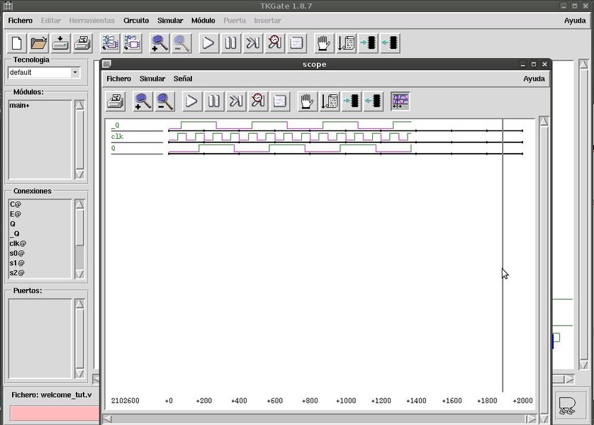
The circuit was simulated using TKGATE Linux software. I was not lucky with QUCS software for this kind of digital simulation. I will give a try in the future. The divider has two ouputs with a 90 degree phase difference.
74HC4052 switching mixer idea cames from the excellent and very educational WEB page of Leif, SM5BSZ:
http://www.sm5bsz.com/linuxdsp/iqmixer.htm
The schematic was adapted for the clock output generated by the 74HC74 circuit.
Let see the digital simulation results:
74HC4052 datasheet provides the truth table:

So, it is a matter of properly connecting Q and /Q signals from the divider to get the right sequence at the 74HC4052 multiplexer/demultiplexer, as we see on the schematics.
Even without RF preamplifier, band pass filters at the antenna input, lowpass filter at the DDS signal and audio amplification, the receiver works reasonably well in the 3.5 MHz band and appears sensitive enough. The receiver works on harmonics of the LO frequency too, so a front end band pass filter is a must for a clean reception. Tunning the DDS at higher frequencies than 3.5*4=14 MHz results in a increasing number of spurs and dummy signals. DDS's clock frequency is 40 MHz, so it is not recommended to work at frequencies higher than 1/3rd the clock frequency.

In the last picture you can see the waterfall on the CW segment on 80 m band. Also you can see strong 50 Hz hamonics on the center of the screen and carriers spaced 1 kHz. Theese carriers are generated into the laptop dirty power supply. In the next picture you can see a cleaner waterfall. A strong 200 km range station, EA1FAQ is tuned in CW mode. Bandwidth is about 500 Hz.

Next step we will add a front end band pass filter at the antenna input and a low pass filter at the DDS output. Finally, the DDS will be replaced by a Si-570 chip signal generator. Keep tuned!
Jim Shaffer, WB9UWA sugested using a voltage divider to rise the input level at the 74HC74 clock and improve sensitivity. I have just done that. A 15k+15k resistor divider did the job and the receiver works just fine withour the bipolar transistor amplifier. Great idea Jim!
I have just added a 5 order low pass filter at DDS output to remove spurs Fclock+-Fout. It is not a state of the art one cause it was in the junk box from older projects. I simulated it and decreased inductance values removing some turns to raise cutt off frequency. It has not got flat response but good to test spurs attenuation.


Current schematic is as follows:

I hace replaced the DDS 40 MHz clock with a 125 MHz (3.3 V one). See the quick and dirty fix:

Surprisingly, DDS worked fine at the first start. Now, DDS generated frequency is Fdisplay*(125/40), so we must change the program in 16F84 PIC microcontroller to have a right reading. We also must change the low pass filter cutoff frequency to something near 60 MHz.


16F84 PIC microcontroller program was modified to match new clock speed (125MHz). It worked inmediately as expected.
A new 5th order low pass fiter has been designed for the DDS output signal. Cutoff frequency is 60 MHz. The schematics is the following:


Jim, WB9UWA suggested to isolate antenna input from ground by removing the winding connection to ground. This way we reduce ground loop problems. A new picture with the new low pass filter can be seen here:

 Now 7, 10 and 14 MHz band signals have been received. I will give more details soon.
I have changed DDS low pass filter (60 MHz cuttof freq now) and now the RTW-receiver works in 3.5, 7, 10 and 14 MHz with no RF filter at all. It exhibit some spurs problems with strong broadcast stations and unwanted signals due to the lack of filtering at all.
I have found some AM detection problems. The AM signals do not depend on any DDS tuned frequency. Hopefully the spurs with be reduced or eliminated when input antenna filters will be present.

Today I was experimenting with the RTW-SDR receiver and I said: well, let's listen to some MW AM stations for hearing local news. I have a strong 585 kHz AM station near my home. So I tuned the DDS to 585*4=2340 kHz. No signal. Ummm, strange, I was really preocupied. I switched my handheld radio on an yes, the station was there at 585 kHz. Another local station is placed at 999 kHz. So I tuned the DDS to 999*4=3996 kHz. Nothing at all. I was really puzzled, I am sure that I have tuned that stations before, but that happened when I used no lowpass filter on the DDS and a bipolar NPN transistor for amplifying DDS signal before 74HC74 clock inputs.
Playing with DDS frecuency up and down searching for the stations, I found them but wooooooow, DDS frequency should be tuned to F*3 instead of F*4. The only test equipment I have is a frequency counter so I did the following test. I tuned DDS at 4000 kHz and place the counter at one of two 74HC74 outputs. Fine, frequency was 4000/4=1000 kHz. But when I placed the counter at the other ouput, frecuency was 4000/3=1333.3 kHz. It seems that there is a critical DDS frequency placed a bit higher from 4 MHz. If DDS generated frequency is greater than that, by four division is made correctly.
I suspected lack of enough signal level at the 74HC74 input. I replaced 150 pF capacitor with a 2n2 one and it worked flawesly. I could even receive the 500 kHz band. Simulation turned out that the was 15 dB of DDS signal attenuation at 4 MHz with 150 pF capacitor, which has got 265 ohms of reactance at 4 MHz, too much indeed.
Last schematic with 2n2 capacitor at the lowpass filter input:

RF filter is a must in any kind of receiver, so I have started designing them. HF band will be divided in the following frequency ranges:
I have just built 3-5 MHz, 5-8.5 MHz and 8.5-13.5 MHz filters. The results are impressive. No dummy stations received at 2*F and 3*F frequency. I use jumpers for "quick and dirty" band change. Without the filters, there were plenty of false signals. False signals had the following easy to recognize caracteristics:
Receiver is very usable now. Ham radio stations are heard clearly. Finding, tunning and listening broadcast stations at 7 MHz is a pleasure. Without the filter, listening to 7 MHz band at night time was a nightmare of false signals and overload.
In the next picture you can see the 7 MHz band plenty of CW stations at night

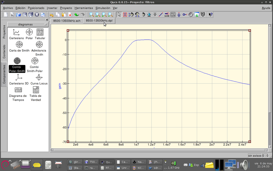
In the following pictures you can see the schematics and frequency response of the filters:


Last prototipe picture:

The schematic:


Getting rid of the DDS board is a must because I need higher LO frequencies to continue experimenting with the mixer. There were plenty of designs in the Internet but I wanted reinventing the wheel again.
The hardware design is very simple. The CPU is a Microchip 18F14k50 20 pin SOIC microcontroller running from a 12 MHz crystal. The chip has got ICSP (In Circuit Serial Programming) for updating the code, USB port and I2C seral interface for programming the Si-570. I have adquired a Si-570 BBC 000141DG (LVDS) from www.sdr-kits.net. Cheap and quick response from Jan Verduyn, G0BBL, great! The maximum frecuency is 280 MHz, minimum frequency is 10 MHz. I have provided a 10 pin output connector that will control the filter board switching relays.
It was the right time for testing my new UV LED light box making my first 2 layers SMD PCB. The results were very good using 20m exposure time. I did not have a 3.3V SOT-223 voltage regulator so I soldered a big TO-220 one in a dirty way. Track width is 0.5 mm.


The PCB has got some stupid mistakes. The 100k reset resistor has to be eliminated or reduced in order to get a proper low voltage RESET at MCLR pin. RESET does not work with the circuit shown. ICSP connector is reversed so Microchip PICKIT2 programer has to be connected upside down. I is not a real problem, but beware about that. I will correct that in future releases. If you need the PCB design I can send it to you. Drop me an email, please.
Once hardware was built, the real fun started. As I did not want to fight against assembler programming, I got Microchip C18 C compiler, I studied the datasheet and got confident with PIKLAB linux programming IDE and C18 compiler. Piklab is a native Linux application and C18 compiler is executed trough wine emulator. The combination works fine but there is a problem, it cannot simulate the code. Piklab uses GPsim for simulating and PIC18F14k50 chip is not supported yet.
MPLABX software is the first Microchip attempt to make a Linux, Windows and Mac programming IDE. It is a Beta6 software but It works well. It relies on Java for working.
I started learning C PIC programming turning on and off some LEDs and once I felt confortably I started studying Si-570 programming trough the I2C interface. It was simpler than I first thought but some stupid PIC configuration bits got me crazy till it worked. USB programming looks harder and I will rely on my friend for that task.
I wrote a simple C code that programm Si-570 chip at the desired frequency. Once it worked, I enabled 2 input pins for up and down 25 kHz frequency change using buttons.The code has got some problems. 38 bit math precision was needed but I used builtin C18 32bit floating point libraries, so that little frequency changes are not allowed. Source code is not well written nor definitive and it has not got USB support yet, but It will allow me to continue experimenting with the receiver.
si-570.c source codeThe schematic:

Ohhhh, long time without writing anything here. It does not mean that I have not made any progress in the receiver, I means that I had less free time to experiment due to my new job and plenty of problems to solve ;-). In the meantime I have bought a cheap Rigol 50 MHz oscilloscope and buil several testing purpose circuits, such as a return loss bridge, step attenuator, impedance measurement device, two DDS generators for receiving testing, diode probes, etc....I will describe such equipment in the future in this WEB page, they are cheap and easy to build. The good thing is that I have learnt a lot of RF theory during this time. I want to thank Leif, SM5BSZ again for his help and the interchanged emails.
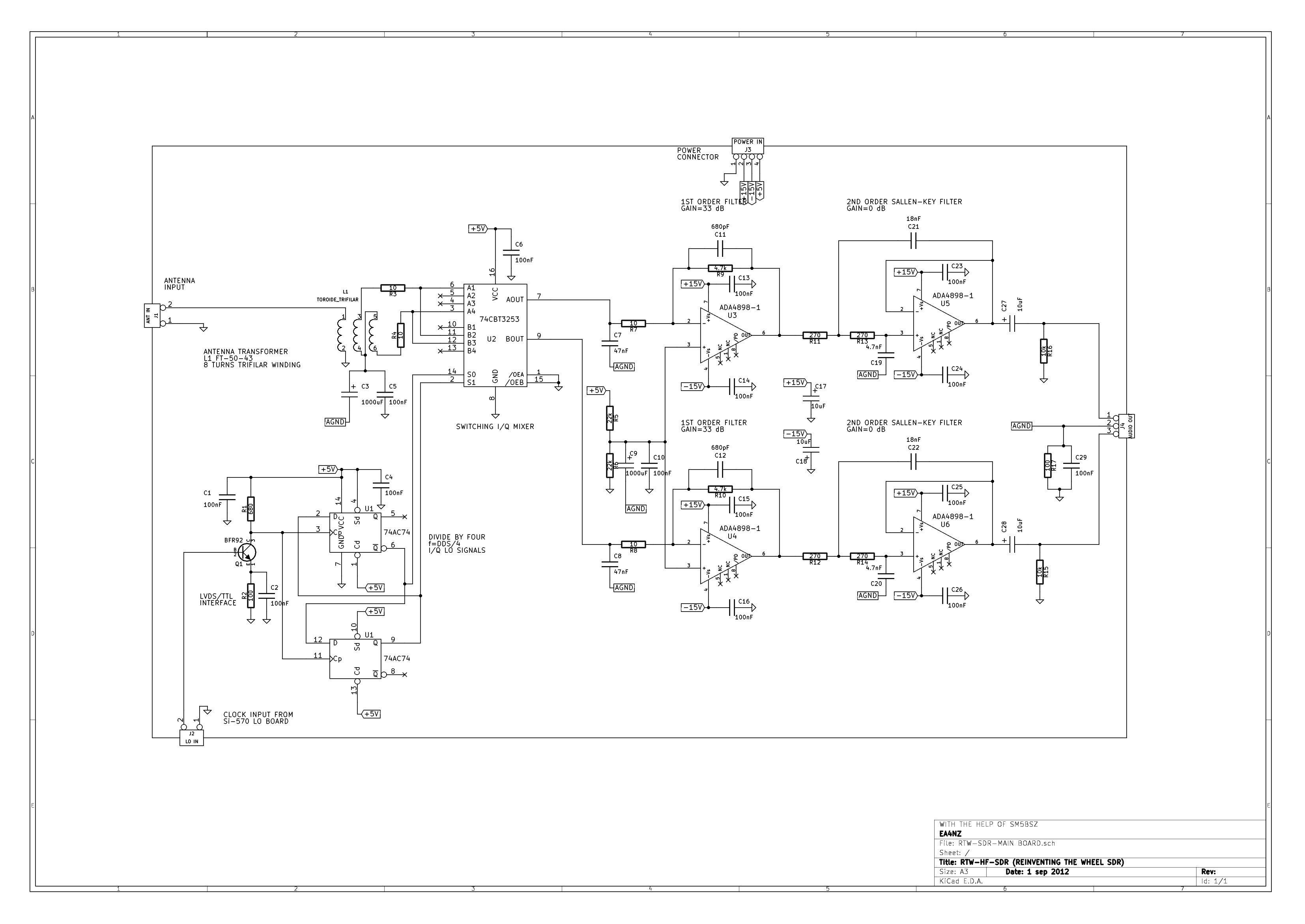
Cause I wanted receiver coverage up to 30 MHz, I redesigned the circuit changing several components:
- A faster multiplexer, 74CBT3253 SOIC chip. This chip only allows 0-5V signals so from now audio signals will be centerd around 2.5V.The receiver worked very well up to 30 MHz but it does not work at 50 MHz. 200 MHz are out of the specifications of the 74AC74 flip-flop. For 50 MHz perhaps I could use a 66.66 MHz LO signal. If we divide by 4 we have 16.67 MHz signal. Such signal times 3 is 50 MHz. I have to test if that works.
I divided the schematic in four pieces:- Main board. It contains the LVDS-TTL interface, 74CBT3253 multiplexer, 74AC74 flipflop and two audio stages (one per channel)
- Filter board. Includes the RF filters, switches, attenuator and RF amplifier. Only the filters are tested, switching elements are not built yet, perhaps in the future they will be substituted by diodes or transistors.
- Local oscillator board. It contains the PIC 18F14K50 Microchip microcontroller, Si-570 generator and USB connector
- Power supply board. It provides +-15V and +-5V DC for the other boards. -5V is not used in this project.
I have also started to desing the main board PCB, but I estimate it will be finished in the next year or two.... hi ;-)


First order and second order Sallen-key filters were calculated using a Libreoffice spreadsheet that was designed using the book Operational Amplifiers For Everyone by Texas Instruments:

To test the performance of the audio filter, I tuned the receiver at 14.000 MHz. I injected a signal using a AD9850 DDS generator and a step RF attenuator. RF level was -25dBm, 18.8 mV peak.The test signal was tuned from 14.000 MHz to 14.200 MHz, in order to get a 0 to 200 kHz tone in the receiver audio output. Signal level was measured with an oscilloscope,

The results were plotted using Libreoffice spreadsheet:


The mixer was simulated using LTSPICE (http://www.linear.com/designtools/software/#LTspice). This software is very fast compared to QUCS in transient simulations. So from now I use QUCS for AC and Sparameter simulation and RF filter design. LTCPICE is my preferred tool for transient simulations. LTSPICE runs perfectly under WINE on Linux.QUCS is a powerful tool where you need to include equations.

That is all for now
Software used:
Bibliography:
  Copyright (c)  2006 Ramiro Aceves .
  Permission is granted to copy, distribute and/or modify this document
  under the terms of the GNU Free Documentation License, Version 1.2
  or any later version published by the Free Software Foundation;
  with no Invariant Sections, no Front-Cover Texts, and no Back-Cover
  Texts.  A copy of the license is included in the section entitled "GNU
  Free Documentation License".